

Introduction
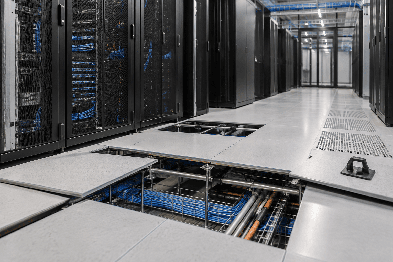
A data center technician is in the cold aisle with a suction-cup tile lifter. A fiber run needs to be rerouted before a migration window closes. Instead of cutting a wall or disturbing the room, she lifts one 600 mm × 600 mm panel, routes the cable through the plenum below, and replaces the tile. The change is made with minimal disruption to the live data hall.
That simple maintenance task explains why raised access floors have remained important for decades. But the engineering assumptions behind them are changing. AI and high-performance computing are introducing racks with much higher power density and concentrated point loads, while liquid-cooling infrastructure is adding new piping, manifolds and equipment requirements.
Why This Matters
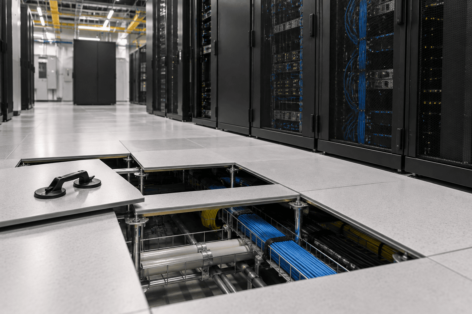
A raised access floor is not just a finish or a convenient cable route. It influences cooling distribution, cable management, maintainability, structural loading, room height and future flexibility. A decision made during design can remain part of the facility for 15–20 years.
Energy and PUE pressure: Underfloor airflow can be an important part of an air-management strategy, so plenum depth, tile selection and containment affect how cooling is distributed.
Capex and change risk: Pedestals, panels, plenum depth and ceiling coordination are difficult to change after the hall is operational.
AI density: High-density racks can create point loads and cooling requirements that exceed the assumptions of older raised-floor halls
The Core Problem: What Has Changed?
For many conventional data halls, the raised floor solved two problems at once: it provided an accessible route for cabling and created a plenum that could distribute conditioned air. Today, the question is more specific: can the floor safely support the equipment and cooling architecture that the next generation of workloads requires?
What Is a Raised Access Floor?
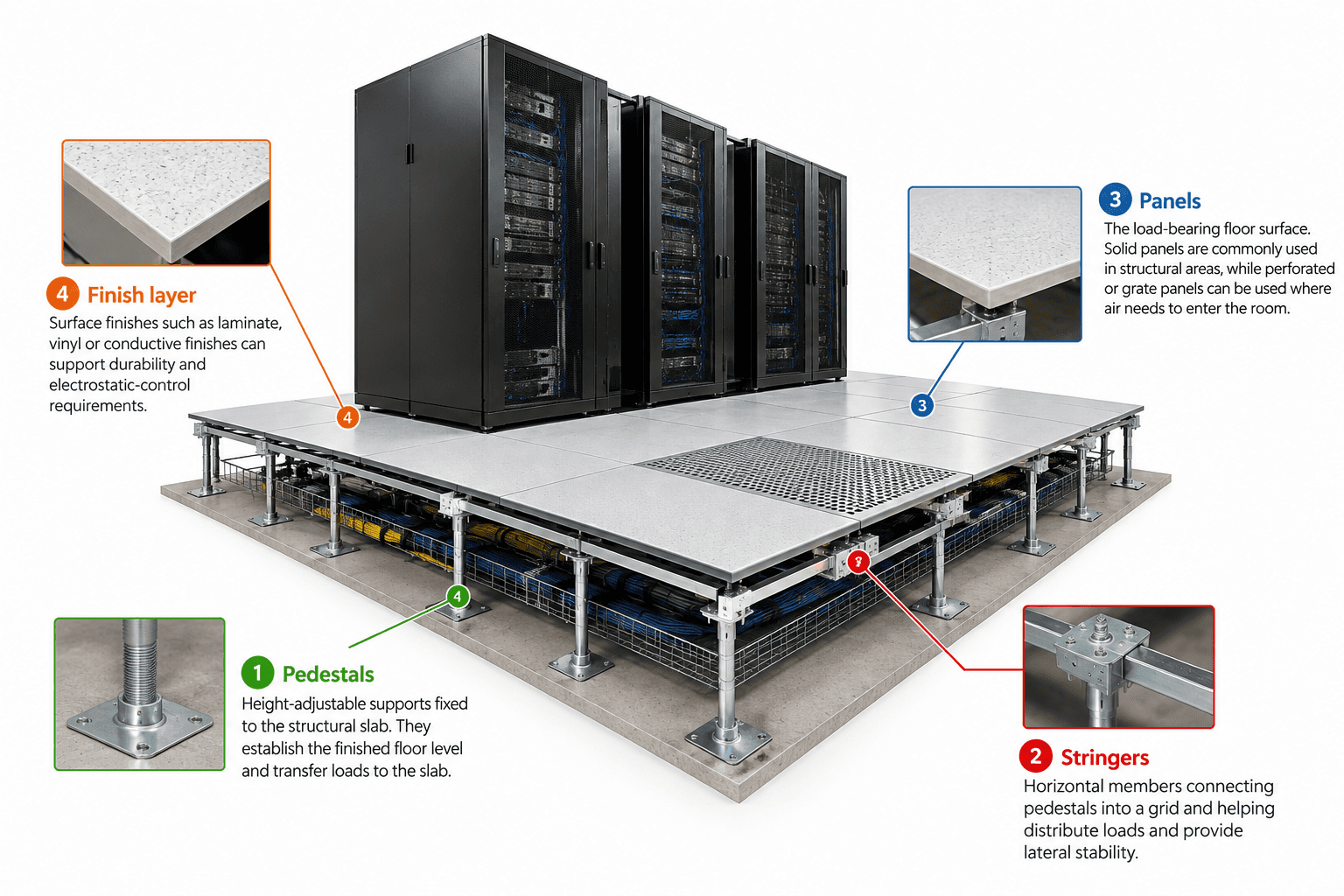
A raised access floor is an elevated panel system installed above the structural slab. Typical systems use 600 mm square panels supported by adjustable steel pedestals, with stringers used where the design requires additional grid stability and load distribution. The space below the panels forms an underfloor plenum.
The Four Main Components
Pedestals: Height-adjustable supports fixed to the structural slab. They establish the finished floor level and transfer loads to the slab.
Stringers: Horizontal members connecting pedestals into a grid and helping distribute loads and provide lateral stability.
Panels: The load-bearing floor surface. Solid panels are commonly used in structural areas, while perforated or grate panels can be used where air needs to enter the room.
Finish layer: Surface finishes such as laminate, vinyl or conductive finishes can support durability and electrostatic-control requirements.
How the Underfloor Plenum Supports Cooling
In an air-cooled configuration, conditioned air is delivered into the underfloor plenum and rises through selected perforated tiles. The air enters the cold aisle, passes through the IT equipment, and leaves the racks as heated exhaust toward the return path.
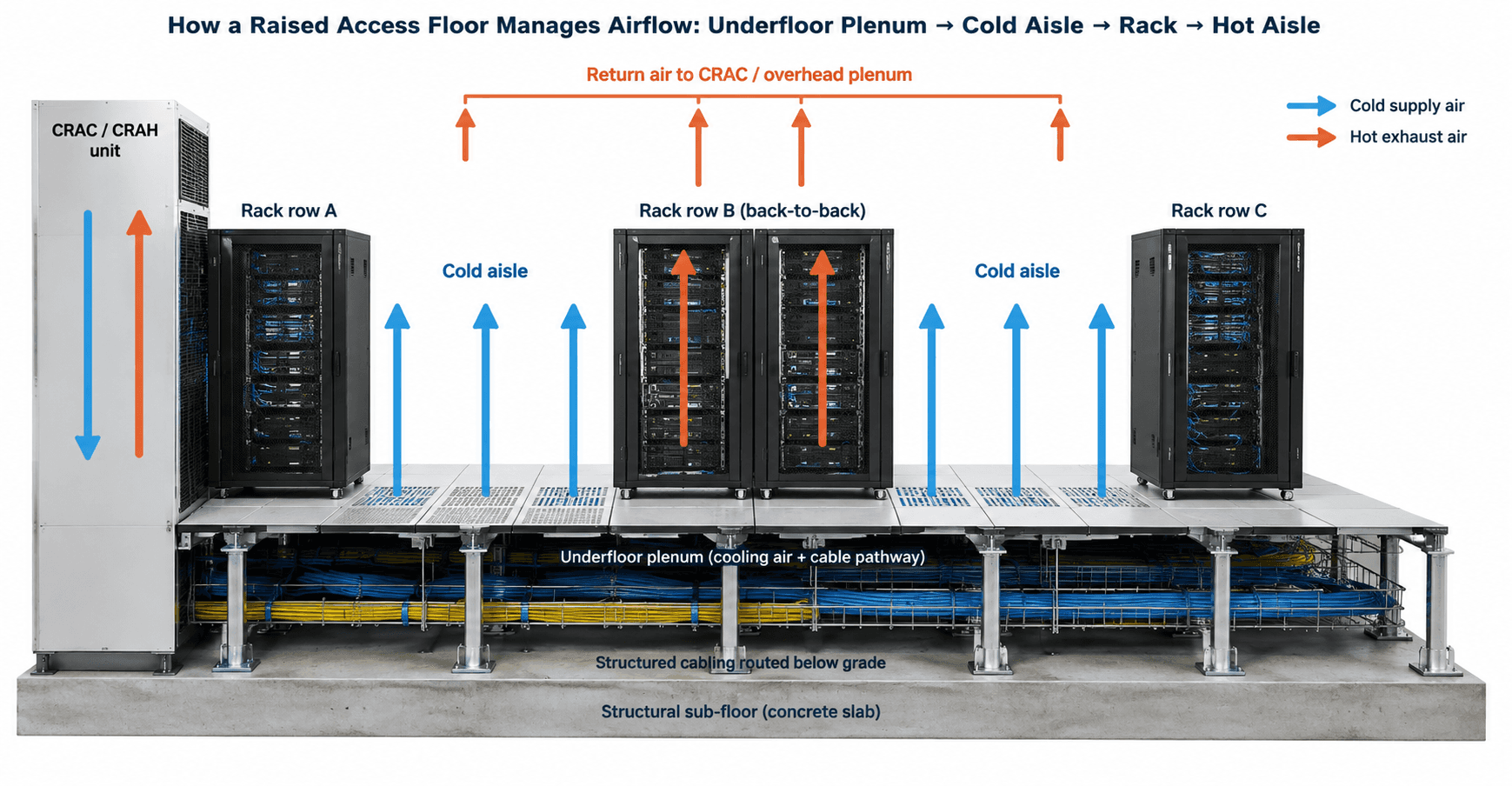
Figure 1 — Underfloor plenum, cold-aisle supply and hot-aisle return in a typical raised-floor data hall.
The Electrical Engineer's Connection
The floor also affects electrical coordination. Underfloor pathways may carry structured cabling and selected electrical services, while modern halls increasingly use overhead busway and cable tray systems. The final arrangement must maintain segregation, access, load paths and maintenance clearances.
DESIGN OPTIONS & ENGINEERING TRADE-OFFS
Two Common Raised-Floor Profiles
Traditional high-profile floors: Approximately 18–36 inches of plenum depth. These systems can provide substantial underfloor space for cabling and airflow but require more structural and vertical space.
Low-profile floors: Approximately 4–12 inches of clearance. They can suit constrained rooms and retrofit applications, but the smaller plenum can limit airflow capacity and service space.
Where Raised Floors Provide Practical Value
Airflow flexibility: Solid and perforated tiles can be repositioned as room layouts change, allowing localized airflow adjustment.
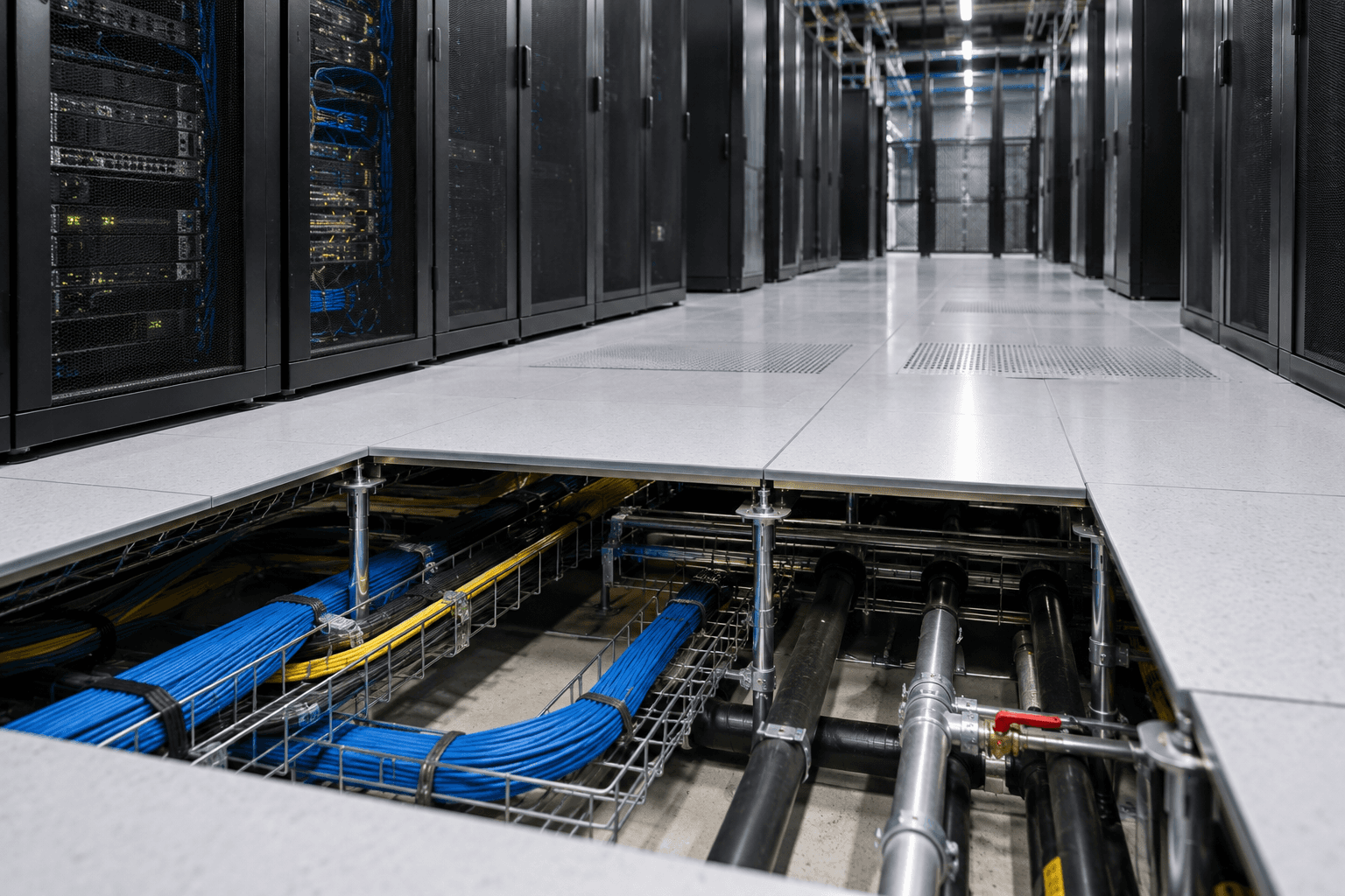
Cable accessibility: The underfloor zone can provide a protected and accessible pathway for data and other services.
Modularity: Tiles can be removed or relocated during equipment changes, reducing disruption to the finished room.
Electrostatic control: Appropriate conductive finishes and grounding arrangements can support ESD-control requirements for sensitive electronics.

Where the Model Becomes Challenging
The same modular system that makes a raised floor easy to change also has defined structural limits. Engineers must distinguish between average distributed loading and concentrated point loading. Pedestal, stringer and panel ratings should be checked against the actual equipment configuration and support arrangement.
The supplied reference identifies a fully configured NVIDIA GB200 NVL72 rack at roughly 1.4–1.5 metric tons on a footprint of under one square metre, illustrating why AI rack loading can become a structural design issue. Project-specific equipment weights and manufacturer load data should always be verified before final design.
A Useful Design Principle
Do not treat raised floor and slab-on-grade as universal, facility-wide alternatives. A mixed strategy can be considered: conventional areas may retain raised floors while high-density zones use reinforced structural solutions suited to their workload and cooling system.
REAL-WORLD SCENARIO
From Conventional IT to an AI Pod
Consider a legacy colocation hall originally designed with a 24-inch raised floor. Over time, rack power increases. The operations team responds by improving containment, changing perforated-tile locations and balancing cooling output. These are exactly the kinds of changes a raised floor makes easier.
Then a customer requests a high-density GPU pod with approximately 80 kW per rack and liquid-cooling infrastructure. At this point, simply increasing airflow may not solve the problem. The existing floor may not have the required point-load capacity, and the plenum was not necessarily designed for the new piping and cooling equipment.
A zone-based response can be more practical than rebuilding the entire hall: reinforce the high-density area, provide structural support for new equipment and manifolds, and introduce liquid-assisted or liquid cooling where required. The remaining conventional IT area can continue using its existing raised-floor strategy.
What This Scenario Teaches Engineers
Start with the workload: Rack density, equipment weight and cooling technology should be defined before the floor system is finalized.
Coordinate structure and MEP together: Floor loading, cable routes, airflow and cooling distribution interact physically.
Design for future zones: A data hall may evolve into multiple thermal and structural zones rather than one uniform environment.
Raised Floor + Electrical + BIM Coordination
For an electrical/BIM team, the floor decision is connected to the complete coordination model. Cable trays, busways, racks, piping, CDUs, structural supports, containment and access routes may all compete for the same physical space.
Model maintenance clearances and access routes early.
Reserve primary routes for electrical and cooling services.
Check elevations and crossings between cable trays, busways and liquid services.
Run clash detection before construction and update the model as the design develops.
DATA, DESIGN CHECKS & ACTIONS
Engineering Checks Before Selecting the Floor
Verify point loads: Use actual equipment weights, footprints, wheel loads where applicable and support conditions not only an average floor loading value.
Check plenum depth: Confirm that the available clearance supports the intended airflow, cable routing, access and other services.
Map the density roadmap: Consider expected rack power and equipment changes over the next three to five years, not only the initial IT fit-out.
Coordinate cooling strategy: Air-cooled, liquid-assisted and liquid-cooled zones can have very different spatial and structural requirements.
Plan electrical distribution: Overhead busway and cable trays may reduce congestion in the underfloor zone and can support future expansion.
What the Reference Data Highlights
The supplied reference describes traditional raised-floor halls, high-density AI racks and hybrid retrofit strategies as part of the same design evolution. It cites typical high-profile plenum depths of 18–36 inches and low-profile systems around 4–12 inches. It also notes that high-density AI equipment can exceed the load assumptions of standard raised-floor systems.
The reference further describes a broader industry shift toward liquid cooling and reinforced structural solutions for AI-dense zones, while retaining raised floors as a practical option for many moderate-density enterprise and colocation applications. These figures and trends should be treated as design discussion inputs and verified against current OEM data, project requirements and structural calculations.
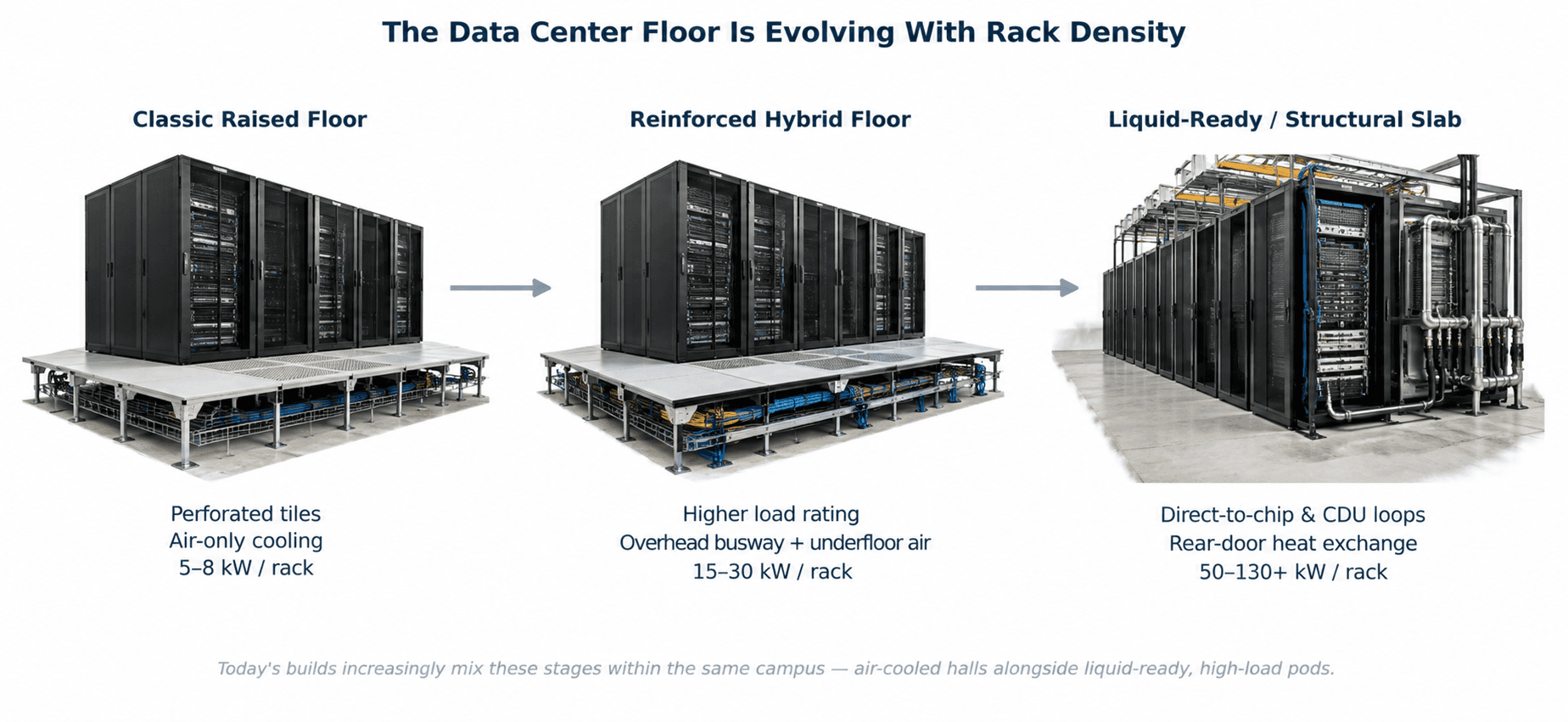
Figure 2 — The data center floor is evolving alongside rack density, from classic air-cooled raised floors toward reinforced and liquid-ready structural solutions.
What Facility Teams Should Do Next
The practical next step is not to choose a floor technology in isolation. Build a coordinated decision matrix around workload, rack density, point load, cooling architecture, cable strategy, maintenance, future expansion and structural capacity.
FUTURE OUTLOOK
Where Raised Access Floors Are Headed
The raised floor is evolving rather than simply disappearing. Future facilities are likely to combine different floor and cooling approaches within the same campus or hall. Conventional air-cooled areas can coexist with high-density zones that require reinforced slabs, liquid cooling, rear-door heat exchange or direct-to-chip systems.
The supplied reference also points toward reinforced pedestal systems, higher floor load ratings and hybrid air-and-liquid distribution concepts. As rack density increases, the floor becomes increasingly connected to structural, mechanical, electrical and BIM decisions.
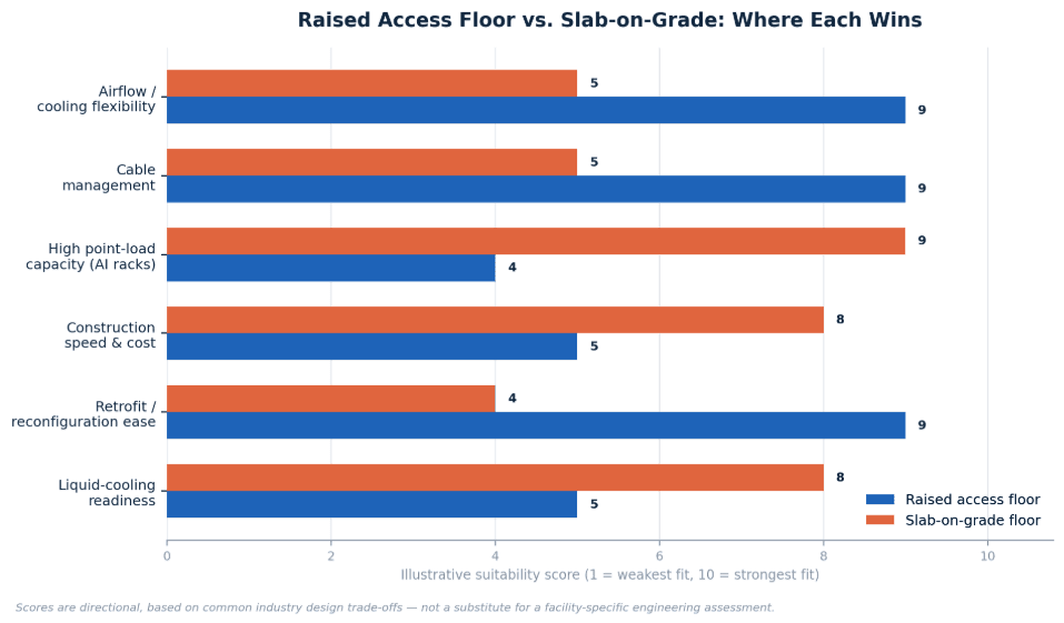
Figure 3 — Directional comparison of raised access floors and slab-on-grade construction across common data-center design priorities. The scores shown are illustrative and are not a substitute for a facility-specific engineering assessment.
Closing Thought
A raised access floor may look like a simple collection of panels and pedestals, but in a data center it can influence cooling, cabling, maintenance, structural capacity and future expansion. The important question is not whether raised floors are old or new. It is whether the floor system matches what the data hall must safely support today and as the workload changes.
Quick FAQs
1. What is the main purpose of a raised access floor in a data center?
It provides an accessible service zone for cabling and can also act as an underfloor air-supply plenum in air-cooled halls.
2. Does every data center need a raised floor?
No. The appropriate solution depends on rack density, cooling architecture, structural loading, cable distribution and project constraints.
3. Why are AI racks changing the floor decision?
High-density AI racks can introduce much higher point loads and concentrated heat loads than many legacy halls were designed to support.
4. Can raised floors and slab-on-grade be used in the same facility?
Yes. A zone-based approach can match different floor systems to different workloads and cooling requirements.
5. What should engineers check first?
Start with actual rack weights and power density, then coordinate structural capacity, cooling, electrical distribution, cable routing and maintenance access.